Vacaero

Manufacturers of heat treating and brazing vacuum furnaces and controls, complete hot zone and vacuum furnace retrofits, thermal spray coatings, plasma, HVOF and paint coating services.

VAC AERO Service Experience Trust
Canada FrançaisAccessibility |
  • Home
  • Company
  • Vacuum Furnaces
  • Thermal Processing
  • Coatings
  • Service & Support
  • Resources
  • Contact Us
  • Request for Quote

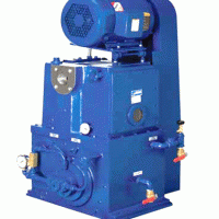
The Oil Sealed Rotary Vacuum Pump

January 4, 2013 by VAC AERO International

The Oil Sealed Rotary Vacuum Pump

Since oil sealed mechanical vacuum pumps started to be commercially available in the 1920s there have been many companies making this type of pump. The oil flooded rotary piston vacuum pump runs at a slow rotational speed and is a heavy duty design. It has been manufactured for about 85 years.

In the early 1900s these pumps were relatively small at up to 40 cfm capacity. By the late 20s and early 30s the industrial revolution was gaining steam and the manufacturers designed larger capacity pumps to suit new applications. By the 1940s rotary piston vacuum pumps were offered in capacities up to 700 cfm. They are known for the ability to keep on running despite ingesting all sorts of contaminants. Kinney claims to have introduced the world’s first rotary pump in 1904, two years after the company was founded. The Kinney document I have just says rotary pump but I presume it was a rotary vane design as other documents say the rotary piston pump design was introduced in about 1909. In 1926 their popular model was the VSD-8811, later to be the KS-47. Current large models are called the ”KT” series.

Grain Size Measurement: The Heyn Intercept Method

December 14, 2012 by George Vander Voort

Grain Size Measurement: The Heyn Intercept Method

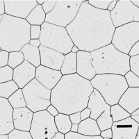
When ASTM standard E 2 was published in 1917, ASTM Committee E-4 on Metallography’s first standard, it described the planimetric method for measuring grain size based upon publications by Zay Jeffries, a founding member of E4; but, E 2 only briefly mentioned the intercept method developed in Germany in an appendix at the end of the standard.

The intercept method suggested by Heyn in 1903 [1] is considerably faster to perform manually which has made it popular, despite the fact that there is no direct mathematical connection between the mean lineal intercept length and G. Both straight lines and circles have been used as templates, plus other shapes.

Grain Size Measurement: The Jeffries Planimetric Method

November 12, 2012 by George Vander Voort

Grain Size Measurement: The Jeffries Planimetric Method

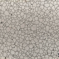
When ASTM standard E 2 was published in 1917, ASTM Committee E-4 on Metallography’s first standard, it described the planimetric method for measuring grain size based upon publications by Zay Jeffries, a founding member of E-4.

Jeffries was a graduate student under the famous Harvard professor, Albert Sauveur. Sauveur published a paper in 1894 where he defined grain structures in terms of the number of grains per square mm at 1X. But, he did not develop details on his method. This method is more tedious to use than the Heyn intercept method because a count of the grains must be made by physically marking the grains as they are counted, when done manually. Experiments were conducted to determine the influence of the number of grains counted per grid application using the Jeffries planimetric procedure of ASTM E 112 with a single test circle of varying size. Results show that this is a viable test method and produced good data down to relatively low count numbers per grid application. Bias was not observed at low counts, only data scatter.

Hot Zone Design for Vacuum Furnaces

October 3, 2012 by VAC AERO International

Hot Zone Design for Vacuum Furnaces

The hot zone is perhaps the most critical feature of a vacuum furnace in terms of its effect on furnace performance and operating cost. There are a variety of hot zone designs and the choice of a design should be based on a careful analysis of specific processing applications. Most vacuum-furnace hot zones consist of four major components: the heating elements and the details on which they are mounted; the insulation package (or heat shields); a surrounding structure that supports the heating elements and insulation package; and a hearth that supports the load during processing.

Most vacuum-furnace hot zones consist of four major components: the heating elements and the details on which they are mounted; the insulation package (or heat shields); a surrounding structure that supports the heating elements and insulation package; and a hearth that supports the load during processing. A hot zone can be constructed in either rectangular or cylindrical form, with the latter being far more prominent in vacuum furnaces today. All hot zones are constructed in modular form for ease of installation into and removal from the vacuum chamber. BY JEFF PRITCHARD

Measurement of Grain Size in Twinned FCC Alloys

September 24, 2012 by George Vander Voort

Measurement of Grain Size in Twinned FCC Alloys

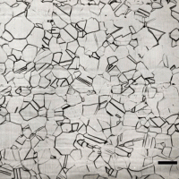
Grain size is probably the most frequent microstructural measurement due to its influence on properties and behavior/service performance. Grain size can be determined by several methods. Chart comparison ratings are probably the most often performed, as this method is fast and simple. But its accuracy is at best ± 1 G value.

An ASTM E-4 interlaboratory round robin test using Plate I of ASTM E 112 showed that chart ratings were biased with the rating being ½ to 1 G value coarser than the actual measured grain size. Similar studies have not been conducted with Plates II or III. Actual measurements of grain size are done by either the planimetric or the intercept methods, as defined in E 112. These are unbiased methods, as long as the grain boundaries were properly delineated by the etchant. Experience has shown that measuring the grain size of BCC metals is much easier than measuring the grain size of FCC metals and alloys that contain annealing twins. ASTM E 112 has two comparison charts for such metals; Plate II for specimens that exhibit a so-called “flat” etch appearance and Plate III for those that exhibit a grain contrast etchant response. Plate III was developed using copper specimens and the images are at 75X, while the other E 112 charts are at 100X. To further confuse the issue, Plate III expresses grain size in terms of d, the average grain diameter, calculated by taking the square root of the average grain area (which is the reciprocal of the number of grains per mm2), rather than as an ASTM grain size number, G.

Measurement of Grain Shape Uniformity

September 15, 2012 by George Vander Voort

Measurement of Grain Shape Uniformity

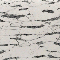
Cold working is well known to change the properties of metals and alloys. Deformation increases the strength of metals but usually reduces it toughness and leads to anisotropy of properties, that is, directionality. Hot working also produces similar affects, the microstructural results after hot work with low finishing temperatures may appear to be the same as from cold working.

Hot rolling of shapes, plate or bar, for example, elongates the nonmetallic inclusions in the deformation direction, which will reduce the isotropy of mechanical properties. Hot working can also lead to segregation being elongated parallel to the deformation direction, which also reduces isotropy. Reducing the finishing temperature, that is, the temperature of the steel at the last deformation pass, will promote “banding” – parallel alignment of the constituents into layers, such as alternate bands of ferrite and pearlite. This also promotes anisotropy of mechanical properties, chiefly toughness and ductility. Strength is not usually affected to a significant degree by banding, compared to toughness and ductility.

Important Considerations for Establishing a New Vacuum Heat Treating Capability

August 28, 2012 by Alan Charky

Important Considerations for Establishing a New Vacuum Heat Treating Capability

Many companies that outsource vacuum heat treating must eventually decide if they would be better served by setting up this capability in-house. Establishing a new heat treating capability requires a significant capital investment in furnace equipment.· However, there are other costs and issues that should be considered when assessing the business case for such a project.· VAC AERO has prepared a few brief guidelines to assist customers who are not well-experienced in heat treating but are assessing the need to establish a heat treating capability. (Download PDF of this article)

Furnace Selection – There are a number of factors that should be considered in selecting the best furnace equipment for a new heat treating operation.

 Size – Vacuum furnaces are available in a wide variety of sizes.  The initial capital outlay and operating costs are in proportion to size.  The furnace chamber must be physically large enough to handle the largest workpiece or load being heat treated, plus an allowance for tooling or fixtures.  To achieve proper heating and cooling in a vacuum furnace, individual workpieces within a load must be evenly distributed.  As a result, the furnace work zone may need to be slightly larger than what might be expected by someone unfamiliar with vacuum heat treating.  The furnace manufacturer can review the customer’s heat treating requirements and advise on the most appropriate size and orientation (horizontal, front-loading or vertical, bottom-loading).  When selecting a furnace size, some thought should also be given to future processing requirements.  It is usually impractical (and sometimes impossible) to enlarge a vacuum furnace if larger heat treating applications develop. 

 Budget: The basic equipment price for most popular smaller and medium sizes of vacuum furnaces will range from $300,000 to $500,000.  Additional costs will likely be incurred for site preparation and installation, auxiliary systems, tooling, staffing, and others.  These additional costs can be in the range of $50,000 to $100,000. 

 Throughput: The amount of work that can be processed in a single furnace load is proportional to the size of the furnace.  Typical vacuum heat treating or brazing cycles range in duration from a minimum of about five hours to much longer cycles, many in excess of twelve hours.  With allowances for loading and unloading time, only two to three complete heat treating cycles are typically completed in a 24 hour period.


  • « Previous Page
  • 1
  • …
  • 21
  • 22
  • 23
  • 24
  • 25
  • …
  • 34
  • Next Page »
  • Vacuum Heat Treating: Education & Training
    • News & Announcements
  • Vacuum Technology with The Heat Treat Doctor
  • Vacuum Pump Technology: Education & Training
  • Metallography with George Vander Voort
  • Q’s and A’s
  • “What’s Hot!” Newsletter
  • Glossary Metallurgical Terms
Vertical vacuum furnace specifications
horizontal vacuum furnace specifications
Vacuum Furnaces
Vacuum Furnace Zone Rebuilds
Technical Articles and Resources

Specialists in Vacuum Furnace Technology - High Quality Vacuum Furnace Manufacturer

COMPANY

  • VAC AERO Products & Services
  • Company History
  • Certificates & Approvals
  • Employment Opportunities
  • Values & Commitment
  • Corporate Sponsorship
  • Corporate Brochure
  • Terms & Conditions of Use
  • Privacy Policy

FURNACE MANUFACTURING

  • Horizontal Furnace Specs
  • Vertical Furnace Specs
  • Hot Zones
  • Control Systems
  • Custom Vacuum Furnaces
  • Quality Control
  • Service & Support
  • Furnace Request For Quote (RFQ) Form

THERMAL PROCESSING

  • Ontario – Plant 1
  • Ontario – Plant 2
  • Quebec – Thermal Processing Division
  • Specific Heat Treating & Brazing Approvals
  • Metallurgical Services Matrix

COATINGS

  • Quebec Coatings Division
  • HVOF Spray System
  • Specific Coating Approvals
  • Metallurgical Services Matrix

SERVICES & SUPPORT

  • Furnace Rebuilds & Upgrades
  • Hot Zone Rebuilds
  • Process Controls Upgrades
  • Ordering Parts
  • Field Service
  • Training Seminars

© Copyright 2016 VAC AERO - All rights reserved. Site Map Contact Terms and Conditions Privacy