Vacaero

Manufacturers of heat treating and brazing vacuum furnaces and controls, complete hot zone and vacuum furnace retrofits, thermal spray coatings, plasma, HVOF and paint coating services.

VAC AERO Service Experience Trust
Canada FrançaisAccessibility |
  • Home
  • Company
  • Vacuum Furnaces
  • Thermal Processing
  • Coatings
  • Service & Support
  • Resources
  • Contact Us
  • Request for Quote

Very Low Loads in Micro-indentation Tests Must Be Avoided

September 8, 2015 by George Vander Voort

Very Low Loads in Micro-indentation Tests Must Be Avoided

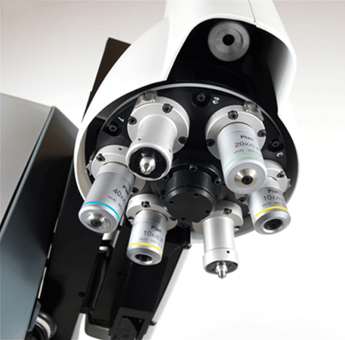
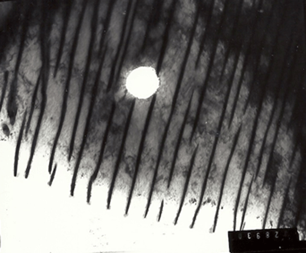
For many years, ASTM E384 has stated that test forces from 1 to 1000 gf can be used to determine the Vickers or Knoop micro-indentation hardness. But, is it realistic to consider using very low test forces when the indents are measured with a light optical microscope? ASTM E92 is being resurrected and changed to cover all test loads, micro- and macro-loads, from 1 gf to 120,000 gf. Most micro-indentation hardness testers manufactured over the last 50 years or more have provided the user with a 10X objective used to find the area of interest for testing and one measurement objective, 40X magnification being the most common. A few testers have offered 50X or 60X objectives to measure the indents. It is rare to find a tester with a multiple objective (and indenter) turret, such as the DuraScan system which has ports for 2 indenters and 4 objectives. But, even with the highest quality 100X objective, indents smaller than ~15 μm in length cannot be measured with adequate precision for realistic work. The ASTM standards should eliminate recommendation of use of test loads <50 gf for Vickers and <20 gf for Knoop.

In both ASTM E384 (Micro-indentation Hardness Test Standard) and the proposed revision and re-instatement of E92 (to cover both Macro- and Micro-Loads for Vickers and Knoop), test forces below 25 gf for both Vickers and Knoop testing are listed as permissible for use. The proposed E92 lists test forces for Vickers macro-testing up to 120 kgf , although no machine built in some time has provided forces above 50 kg. The original Vickers testers made in England did use test forces up to 120 kgf, but that is a historical fact, irrelevant today.

Using the Control Chart Approach to Evaluate Hardness Tester Performance

August 11, 2015 by George Vander Voort

wrought-7-Mo wsThe control chart data analysis approach is an ideal method to evaluate the quality of test data using a specific tester, such as a microindentation hardness tester, over a period of usage time. The method described in ASTM E2554 was used for this work.  This analysis is done by plotting a means and a standard deviation control chart of the weekly/periodic verification data obtained with certified hardness test blocks at a specific test force and a specific hardness level. The method is illustrated using a Knoop hardness test block certified at a test force of 500 gf and with a long diagonal length of 116.18 μm (527.1 HK). From this data, one can easily calculate the uncertainty of the measurements.

The Control Chart method described in ASTM E2554, and discussed by Neil Ullman, is an ideal procedure for evaluating the performance of hardness testers as it will detect any abnormalities that may occur with usage time. The control chart concept was first developed by Walter Shewhart in 1931 to define the state of statistical control and to detect random or special problems. In 1933, ASTM Committee E1 produced STP 15, “ASTM Manual on Presentation of Data.” This was supplemented in 1935 with “Presentation ± Limits of Uncertainty of an Observed Average,” the first use of the term “uncertainty” in statistical analysis of test data. Today, additional information on control charts is provided by E2587.

Image caption: Microstructure of wrought 7-Mo Plus duplex stainless steel (Fe – <0.03% C – 27.5% Cr – 4.2% Ni – 1.75% Mo – 0.25% N) electrolytically etched with aqueous 20% NaOH (3 V dc, 5 s) to color the ferrite blue. There is some light yellow-tan coloring of the austenite. The average Knoop hardness of the austenite was 361.8 HK and that of the ferrite was 263.5 HK.  Magnification bar is 20 µm in length. 7-Mo Plus is a registered trademark of Carpenter Technology Corp., Reading, Pennsylvania.

Measurement of the Volume Fraction of Beta Phase in Naval Brass

July 1, 2015 by George Vander Voort

Measurement of the Volume Fraction of Beta Phase in Naval Brass

Measurement of the amount of phases or constituents in metals and alloys is probably the most commonly performed quantitative microstructural test. The amount present is usually referred to as the volume fraction, although it is rarely expressed as a fraction but usually as a percentage. The volume fraction, or VV, in stereological terms, is the volume per unit volume of the phase or constituent. However, there is no simple direct way to measure the volume fraction. Instead we measure the area fraction, AA, a lineal fraction, LL, or a point fraction, PP, which can be measured and correlate with the volume fraction: VV = AA = LL = PP (1).

Areal analysis was first described by Delesse, a French geologist, in 1848. As the minerals were rather coarse in size, he could measure the area fraction of the grains of interest compared to the total two-dimensional area. As microstructures are rather fine in size, this is not a simple method to perform manually. Delesse suggested that a linear ratio of dimensions could also be used, but he thought that the accuracy would not be as good and did not try to develop a lineal analysis method. Rosiwal, a German geologist, was the first to publish a lineal fraction method in 1898 to assess the volume fraction. The point counting method to assess the volume fraction came much later and was proposed by Thompson in 1933, by Glagolev in 1933 and by Chalkey in 1943 – each working in different countries and different fields of science.

Metallographic Procedures for Cast Irons

June 10, 2015 by George Vander Voort

Metallographic Procedures for Cast Irons

Metallographic techniques for cast irons are similar to those for steels; with the exception that graphite retention is a more challenging task. Recommended procedures to prepare cast irons are given. Colloidal silica is an excellent final polishing abrasive for many metals and alloys. However, for pearlitic cast iron grades, colloidal silica often produces small etch spots on the specimen surface. In this case, OP-AN alumina suspension yields excellent results, much better than standard alumina abrasive powders made by the calcination process. Examples of cast iron structures revealed using a variety of etchants is presented.

New concepts and new preparation materials have been introduced that enable metallographers to shorten the process while producing better, more consistent results. But first, the specimens must be sectioned. Many metallographers do not use a blade designed for metallography work, and the depth of damage will be much greater when production-type abrasive saws are used. So, as a first rule, produce a cut with the least possible amount of damage. If an automated device is used that holds a number of specimens rigidly (central force), then the first step must remove the sectioning damage on each specimen and bring all of the specimens in the holder to a common plane. This first step is often called “planar grinding.” SiC paper can be used for this step, although more than one sheet may be needed. Alternatively, the metallographer could use MD-Piano 120 or 220 (for specimens with hardness >150 HV) for the initial grind, followed (if desired) by MD-Piano 600 for a second grinding step. If the cast iron has a low hardness (<250 HV), one can planar grind with MD Primo 220. Alternatively, MD-Allegro could also be used to planar grind for specimens >150 HV hardness. If the hardness is <150 HV, MD-Largo can be used.

Deformation and Annealing of Cartridge Brass

May 11, 2015 by George Vander Voort

Deformation and Annealing of Cartridge Brass

Copper and its alloys are among the most malleable metals and alloys in existence. Cartridge brass, Cu – 30% Zn, has been used for many years to produce cartridge cases for ammunition due to its superior cold forming characteristics. This article shows the microstructure and hardness of cartridge brass from the fully annealed to the heavily cold worked condition. Then, it illustrates the influence of annealing temperature and time on removing the effect of the cold work and returning the alloy to a very low hardness annealed structure.

Cartridge brass, Cu – 30% Zn, is a single-phase Cu-based alloy where the addition of zinc increases the strength of copper by solid solution strengthening. The maximum solubility of zinc in copper at ambient temperature is slightly above 30% Zn. Higher levels of Zn, for example, 40% Zn, produce two phased α-β brass which is less malleable than the single phase, α-Cu cartridge brass. Cartridge brass, as the name states, has been used for many years to make cartridges for bullets due to its excellent formability and good cold formed mechanical properties. As an example, Figure 1 shows the microstructure of the starting cup with an annealed α-Cu grain structure, exhibiting annealing twins, used to cold form cartridge cases. Figure 2 shows the firing pin end of a formed 338 caliber cartridge case revealing a heavily cold worked microstructure. Color etching is far more effective than black & white etching to reveal the complete grain structure and deformation. Comparisons of color vs. B&W etching will be presented later.

The Interlamellar Spacing of Pearlite

April 9, 2015 by George Vander Voort

The Interlamellar Spacing of Pearlite

The interlamellar spacing of pearlite is a very important microstructural parameter for steels containing pearlite, and becomes more important as the pearlite content increases towards a fully pearlitic microstructure. As the amount of pearlite in ferrite-pearlite microstructures increase, so does the strength, but toughness and ductility decrease. For a fully pearlitic steel, as the interlamellar spacing becomes finer, strength, toughness and ductility all increase. Consequently, in structure-property correlations it is important to measure the interlamellar spacing. This paper reviews procedures for performing such measurements. Due to the fineness of the spacing, either SEM images or TEM images of replicas or thin foils can be utilized. The range of spacings in a given specimen will be much narrower if the pearlite in the steel was formed isothermally rather than transformed over a range of temperatures, as in as-rolled or normalized steels.

Metallographic Imaging Modes

March 1, 2015 by George Vander Voort

5 ws
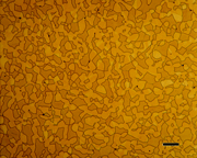
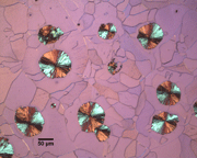
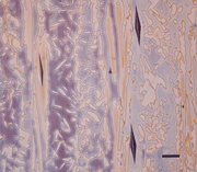
The reflected light microscope is the most commonly used tool for the study of the microstructure of metals. It has long been recognized that the microstructure of metals and alloys has a profound influence on many of their properties. Mechanical properties (strength, toughness, ductility, etc.) are influenced much more than physical properties (many are insensitive to microstructure).

The structure of metals and alloys can be viewed at a wide range of levels – macrostructure, microstructure, and ultra-microstructure. Microstructural examination should always begin with the light microscope progressing from low magnifications to higher magnifications, followed by the use of electron instruments, as needed. In the study of microstructure, the metallographer determines what phases or constituents are present, their relative amounts, and their size, spacing, morphology and arrangement. The microstructure is established based upon the chemical composition of the alloy and the processing steps. A small specimen is cut from a larger mass (for example: a casting, forging, rolled bar, plate, sheet, or wire) for evaluation.

  • « Previous Page
  • 1
  • 2
  • 3
  • 4
  • …
  • 8
  • Next Page »
  • Vacuum Heat Treating: Education & Training
    • News & Announcements
  • Vacuum Technology with The Heat Treat Doctor
  • Vacuum Pump Technology: Education & Training
  • Metallography with George Vander Voort
  • Q’s and A’s
  • “What’s Hot!” Newsletter
  • Glossary Metallurgical Terms
voort
Vertical vacuum furnace specifications
horizontal vacuum furnace specifications
Vacuum Furnaces
Vacuum Furnace Zone Rebuilds
Technical Articles and Resources

Specialists in Vacuum Furnace Technology - High Quality Vacuum Furnace Manufacturer

COMPANY

  • VAC AERO Products & Services
  • Company History
  • Certificates & Approvals
  • Employment Opportunities
  • Values & Commitment
  • Corporate Sponsorship
  • Corporate Brochure
  • Terms & Conditions of Use
  • Privacy Policy

FURNACE MANUFACTURING

  • Horizontal Furnace Specs
  • Vertical Furnace Specs
  • Hot Zones
  • Control Systems
  • Custom Vacuum Furnaces
  • Quality Control
  • Service & Support
  • Furnace Request For Quote (RFQ) Form

THERMAL PROCESSING

  • Ontario – Plant 1
  • Ontario – Plant 2
  • Quebec – Thermal Processing Division
  • Specific Heat Treating & Brazing Approvals
  • Metallurgical Services Matrix

COATINGS

  • Quebec Coatings Division
  • HVOF Spray System
  • Specific Coating Approvals
  • Metallurgical Services Matrix

SERVICES & SUPPORT

  • Furnace Rebuilds & Upgrades
  • Hot Zone Rebuilds
  • Process Controls Upgrades
  • Ordering Parts
  • Field Service
  • Training Seminars

© Copyright 2016 VAC AERO - All rights reserved. Site Map Contact Terms and Conditions Privacy