Vacaero

Manufacturers of heat treating and brazing vacuum furnaces and controls, complete hot zone and vacuum furnace retrofits, thermal spray coatings, plasma, HVOF and paint coating services.

VAC AERO Service Experience Trust
Canada FrançaisAccessibility |
  • Home
  • Company
  • Vacuum Furnaces
  • Thermal Processing
  • Coatings
  • Service & Support
  • Resources
  • Contact Us
  • Request for Quote

Martensite and the Control of Retained Austenite

May 29, 2014 by George Vander Voort

Martensite and the Control of Retained Austenite

Formation of martensite in fine-grained steels is probably the most common goal in heat treatment of components. The carbon content of the parent austenite phase determines whether lath (low-carbon) or plate (high-carbon) martensite, or mixtures of the two will be produced, assuming the quench rate and steel hardenability are adequate for full hardening. Lath martensite produces higher toughness and ductility, but lower strengths, while plate martensite produces much higher strength, but may be rather brittle and non-ductile.

For a given alloy content, as the carbon content of the austenite increases, the martensite start, Ms, temperature and the martensite finish, Mf, temperature will be depressed which results in incomplete conversion of austenite to martensite. When this happens retained austenite, which may be either extremely detrimental or desirable under certain conditions, is observed.  The amount of retained austenite present depends upon the amount of carbon that can be dissolved in the parent austenite phase and the magnitude of the suppression of the Ms and Mf temperatures. This paper examines the conditions under which austenite is retained and the problems associated with it presence, with detecting it and with measuring it.

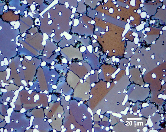
Determining the Nodularity of Graphite in Ductile Iron Using ASTM E2567

May 7, 2014 by George Vander Voort

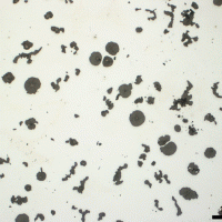
Determining the Nodularity of Graphite in Ductile Iron Using ASTM E2567

ASTM Committee E-4 on Metallography began a program to develop a test method for rating the nodularity of graphite in ductile iron in 1986. The initial effort centered upon using the sphericity equation to assess the shape. However, an interlaboratory study showed that the perimeter measurement varied with the magnification used. A perimeter-free shape factor based on the maximum Feret’s diameter was determined to be magnification independent and reliable.

Additionally, two types of “convex perimeters” were proposed over the ensuing years, but they were demonstrated to be highly biased towards yielding high nodularity ratings regardless of the irregularity of the particle’s shape. The study reported here compared the use of the maximum Feret’s diameter in the shape equation to the mean Feret’s diameter, 100X vs. 200X, a minimum shape factor limit for a particle to be a nodule of 0.5 vs. 0.6, and calculation of an area-based vs. a number-based % nodularity.

Fracture of a 17th Century Japanese Helmet

April 7, 2014 by George Vander Voort

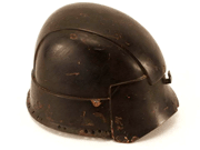
Fracture of a 17th Century Japanese Helmet

There was a crack in the helmet which is not visible in this image (some associated damage can just be seen in the lower left side of the helmet visor). The crack was opened and the fracture began at a streak with mostly intergranular fracture and then propagated by cleavage as shown below.

Note the intergranular fracture in the center foreground. The walls show transgranular cleavage the propagated from the intergranular origin. Next to the fracture, we see a region of columnar grains at the surface with a small region of finer, more equiaxed grains below and the very coarse columnar grains blow that, as shown below.

Influence of the Equations Defining HV and HK on Precision

March 9, 2014 by George Vander Voort

Influence of the Equations Defining HV and HK on Precision

The basic equations defining (see equations 1 and 2) the Knoop (HK) and Vickers (HV) hardness, where the applied force is multiplied by a geometric constant and then divided by the long diagonal squared or the mean diagonal squared, respectively, cause an inherent problem in measuring small indents, that is diagonals ≤20 µm in length.  Figure 1 shows the calculated relationship between the diagonal and load and the resulting hardness for Knoop indents while Figure 2 shows this relationship for Vickers indents. As the test load decreases, and the hardness rises, the slope of the curves for diagonal versus hardness becomes nearly vertical. Hence, in this region, small variations in diagonal measurements will result in large hardness variations.

If we assume that the repeatability of the diagonal measurement by the average user is about ±0.5 µm, which is quite reasonable, and we add and subtract this value from the long diagonal length or the mean diagonal length, we can then calculate two hardness values. The difference between these values is ΔHK and ΔHV, shown in Figures 3 and 4. From these two figures, we can see how the steepness of the slopes shown in Figures 1 and 2 will affect the possible range of obtainable hardness values as a function of the diagonal length and test force for a relatively small measurement imprecision, ±0.5 µm. These figures show that the problem is greater for the Vickers indenter than for the Knoop indenter for the same diagonal length and test force. For the same specimen and the same test force, the long diagonal of the Knoop indent is 2.7 times greater than the mean of the Vickers’ diagonals, as shown in Figure 5.

Propeller Shaft of the USS Monitor

February 10, 2014 by George Vander Voort

Propeller Shaft of the USS Monitor

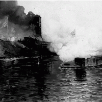
March 9, 1862 marks the date when the USS Monitor and the CSS Virginia (formerly the USS Merrimack) fought an indecisive naval battle at Hampton Roads that changed naval warfare from wood and sails to iron and steam. The USS Monitor sunk off the Outer Banks of North Carolina during a storm on December 31, 1862 but its remains were discovered in 1973. The wreck site, the Monitor National Marine Sanctuary, is managed by the National Oceanic and Atmospheric Administration (NOAA).

The Confederates began construction of an “ironclad” ship at the Gosport Yard of Hampton Roads in 1861. This was well known to the Union Navy Department. The US Army had actually launched ironclad gunboats in the summer of 1861 to patrol the Mississippi River; but none were available in the east to counter the Virginia. On August 3, 1861, Gideon Wells (Secretary of the Navy) requested design proposals for ironclad warships. Swedish inventor John Ericsson had designed an ironclad in 1854 for Napoleon III that incorporated a revolving cupola turret. Cornelius Bushnell promoted this design to Abraham Lincoln.

Metallographic Examination of Bronze Bracelets from Hasanlu

January 14, 2014 by George Vander Voort

Metallographic Examination of Bronze Bracelets from Hasanlu

Hasanlu is an early Iron Age settlement located in northwestern Iran. It dates back to the second millennium B.C., ~1450 B.C., until it was destroyed around 800 B.C. Although the site attracted the attention of the British archeologist Sir Aurel Stein due to artifacts recovered from burial mounds in the 1930s, it was not given substantial attention until the discovery of the “Hasanlu Golden Bowl” in 1958. The Hasanlu archeology project began in 1957 and was greatly stimulated by this discovery. It ended in 1977. The excavations were sponsored by The University of Pennsylvania Museum and the Metropolitan Museum of Art of New York in cooperation with the Archeological Service of Iran.

The author obtained six specimens from the University of Pennsylvania Museum. The six specimens consisted of three cast (No. 1) and three wrought bronze bracelet sections (Nos. 2-4), as defined in Table 1. The three cast specimens were from the same bracelet. For simplicity, they will be referred to as specimens 1, 2, 3 and 4. As there are three specimens of the cast bracelet in mount 1 (HAS 60-617), they will be referred to by their size. The chemical analysis shows that they are similar in composition although the tin content of the fourth specimen is somewhat higher than the other three.

Obtaining Consistent Vickers Hardness at Loads ≤ 100 Grams Force

December 6, 2013 by George Vander Voort

Obtaining Consistent Vickers Hardness at Loads ≤ 100 Grams Force

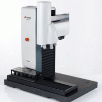
One of the most serious limitations to Vickers hardness testing in the micro-load range (10-1000 gf or 0.098-9.81 N) has been the variability in measured hardness with loads ≤ 100 gf (≤ 0.98 N). In the literature four HV-load trends have been reported for this range.  In the order of most common to least common, the trends are: the hardness decreases with decreasing load; the hardness increases slightly and then decreases; the hardness increases with decreasing load; and, the hardness is constant. Many publications have concentrated on the most common trend and attributed it to material factors. Samuels [1] stated, however, that these problems were due to microscope limitations, such as limited contrast and resolution, and visual perception limitations. At the same symposium, Westrich [2] showed that the SEM could be used to measure small Vickers indents and yield virtually constant hardness as a function of load.

  • « Previous Page
  • 1
  • 2
  • 3
  • 4
  • 5
  • 6
  • …
  • 8
  • Next Page »
  • Vacuum Heat Treating: Education & Training
    • News & Announcements
  • Vacuum Technology with The Heat Treat Doctor
  • Vacuum Pump Technology: Education & Training
  • Metallography with George Vander Voort
  • Q’s and A’s
  • “What’s Hot!” Newsletter
  • Glossary Metallurgical Terms
voort
Vertical vacuum furnace specifications
horizontal vacuum furnace specifications
Vacuum Furnaces
Vacuum Furnace Zone Rebuilds
Technical Articles and Resources

Specialists in Vacuum Furnace Technology - High Quality Vacuum Furnace Manufacturer

COMPANY

  • VAC AERO Products & Services
  • Company History
  • Certificates & Approvals
  • Employment Opportunities
  • Values & Commitment
  • Corporate Sponsorship
  • Corporate Brochure
  • Terms & Conditions of Use
  • Privacy Policy

FURNACE MANUFACTURING

  • Horizontal Furnace Specs
  • Vertical Furnace Specs
  • Hot Zones
  • Control Systems
  • Custom Vacuum Furnaces
  • Quality Control
  • Service & Support
  • Furnace Request For Quote (RFQ) Form

THERMAL PROCESSING

  • Ontario – Plant 1
  • Ontario – Plant 2
  • Quebec – Thermal Processing Division
  • Specific Heat Treating & Brazing Approvals
  • Metallurgical Services Matrix

COATINGS

  • Quebec Coatings Division
  • HVOF Spray System
  • Specific Coating Approvals
  • Metallurgical Services Matrix

SERVICES & SUPPORT

  • Furnace Rebuilds & Upgrades
  • Hot Zone Rebuilds
  • Process Controls Upgrades
  • Ordering Parts
  • Field Service
  • Training Seminars

© Copyright 2016 VAC AERO - All rights reserved. Site Map Contact Terms and Conditions Privacy