Vacaero

Manufacturers of heat treating and brazing vacuum furnaces and controls, complete hot zone and vacuum furnace retrofits, thermal spray coatings, plasma, HVOF and paint coating services.

VAC AERO Service Experience Trust
Canada FrançaisAccessibility |
  • Home
  • Company
  • Vacuum Furnaces
  • Thermal Processing
  • Coatings
  • Service & Support
  • Resources
  • Contact Us
  • Request for Quote

Decarburization

September 24, 2013 by George Vander Voort

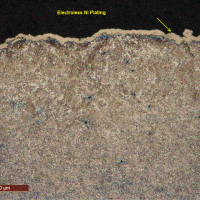
Decarburization

Decarburization occurs when carbon atoms at the steel surface interact with the furnace atmosphere and are removed from the steel as a gaseous phase (1-8). Carbon from the interior will then diffuse towards the surface, that is, carbon diffuses from a region of high concentration to a region of low concentration to continue the decarburization process and establish the maximum depth of decarburization (MAD).

Because the rate of carbon diffusion increases with temperature when the structure is fully austenitic, the MAD will increase as the temperature increases above the Ac3. For temperatures in the two phase region, between the Ac1 and Ac3, the process is more complex. The diffusion rates of carbon in ferrite and in austenite are different and are influenced by temperature and composition.

Methanol Pipeline Failure in the Canyon Express Pipeline System

June 17, 2013 by George Vander Voort

Methanol Pipeline Failure in the Canyon Express Pipeline System

The Canyon Express Pipeline System (CEPS) was started up in November 2002 in the Gulf of Mexico, south of Louisiana. It is owned by six oil companies and collects hydrocarbons from ten wells at depths of ~6100, 7100 and 7200 feet.

The flow line system consists of two 12” diameter gas pipelines (“east” and “west”) connected to a header system, which carries the hydrocarbons 57 miles north to a fixed platform, the Canyon Station, in about 500 feet of water. Tankers come into the Canyon Station to fill up and carry the hydrocarbons to refineries. Just west of the “east” flow line is a 2.875” diameter, X-70 line pipe that carries methanol from the station to the header where it is injected to prevent freezing of the hydrocarbons. To the left of the methanol line is a 6” diameter umbilical line containing electrical power and hydraulic lines.

Measuring Inclusion Content by ASTM E 1245

June 7, 2013 by George Vander Voort

table-1-wsOver the past forty-plus years, steelmakers have introduced improved practices for reducing the inclusion content of steels. The success of these practice changes can be monitored in a variety of ways. Chemical analysis of the bulk sulfur and oxygen contents provides a relatively simple means to assess the impact of these changes. However, microscopical test methods are still needed to assess the nature of the inclusions present.
Traditional chart-based measurement methods have wide acceptability, and their data are well understood by both purchaser and producer for heat acceptance purposes. These methods do have inherent weaknesses which limit their usefulness for quality control, SPC, and database applications. Image analysis-based chart measurements are an improvement over manually generated chart ratings, but the data still does not lend itself to databases and statistical comparisons. ASTM Committee E-4 on Metallography has developed a stereologically-based image analysis standard test method, E 1245, which provides the necessary data in a form which is easily databased and analyzed statistically. The presentation will describe E 1245 and show how data from different heats and melting practices can be compared statistically to ascertain valid test differences.

Grain Size Measurements by the Triple Point Count Method

March 7, 2013 by George Vander Voort

Grain Size Measurements by the Triple Point Count Method

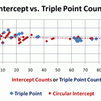
Aside from the well-known grain size measurement techniques using either the planimetric methods of Jeffries or Saltykov, or the intercept method of Heyn, Hilliard and Abrams, one can measure the grain size through a count of grain-boundary triple point intersections within a known area through the use of Euler’s law. This technique has rarely been used but it should be possible to do such a count by image analysis. In general, measurements based on point counts (0 dimensional) are less subject to errors than lineal measurements (one-dimensional) which are less subject to error than areal measurements (two-dimensional). By George Vander Voort

Measuring the Grain Size of Specimens with Deformed Grains

February 4, 2013 by George Vander Voort

Measuring the Grain Size of Specimens with Deformed Grains

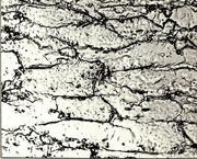
If a specimen has been cold worked, or it did not recrystallize after hot working, the grains will not be equiaxed and extra care must be taken when assessing the specimen’s grain size. Always test a longitudinally oriented plane first to determine if the grains are, or are not, equiaxed.

A low-carbon sheet steel was tested in the as-received condition (reportedly annealed), and after cold reductions in thickness of 12, 30 and 70%. Above 70% reduction, it can be quite difficult to reveal the ferrite grain boundaries well enough to get a precise measurement. Measurements were made on the three principal planes using the Jeffries planimetric method, the Abrams three-circle intercept method and the intercept method using directed parallel test lines.

Grain Size Measurement: The Saltykov Rectangle

January 10, 2013 by George Vander Voort

Grain Size Measurement: The Saltykov Rectangle

The two previous articles covered methods for measuring grain size that have been incorporated into ASTM E112 for many years. The Jeffries planimetric method was introduced into standard E2 in 1917 – Committee E-4’s first standard. Zay Jeffries was a founding member of the committee and had published several articles about the method, which he learned from his PhD advisor, Albert Sauveur, the dean of American metallographers.

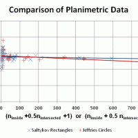
This method is precise, but a bit slow for production work because the grains must be marked off as they are counted manually. The method, however, can be modified for image analysis work. The second method was the Heyn intercept method, which was developed in Germany in 1903 and was mentioned briefly in ASTM E2, but not described in detail, when published in 1917. The intercept method was later modified by John Hilliard and then by Halle Abrams. The Abrams three-circle intercept method is used in production work as the intercepts (or intersections) do not need to be marked off on a template when counted. But, the writer recently has introduced the Saltykov rectangle to E112 as it can yield accurate grain size measurements down to fewer counts per field than the other two methods. As with the Jeffries method, the Saltykov method does require marking of the grains for accurate counting, although it, too, can be used by image analysis.

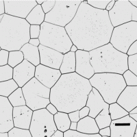
Grain Size Measurement: The Heyn Intercept Method

December 14, 2012 by George Vander Voort

Grain Size Measurement: The Heyn Intercept Method

When ASTM standard E 2 was published in 1917, ASTM Committee E-4 on Metallography’s first standard, it described the planimetric method for measuring grain size based upon publications by Zay Jeffries, a founding member of E4; but, E 2 only briefly mentioned the intercept method developed in Germany in an appendix at the end of the standard.

The intercept method suggested by Heyn in 1903 [1] is considerably faster to perform manually which has made it popular, despite the fact that there is no direct mathematical connection between the mean lineal intercept length and G. Both straight lines and circles have been used as templates, plus other shapes.

  • « Previous Page
  • 1
  • …
  • 3
  • 4
  • 5
  • 6
  • 7
  • 8
  • Next Page »
  • Vacuum Heat Treating: Education & Training
    • News & Announcements
  • Vacuum Technology with The Heat Treat Doctor
  • Vacuum Pump Technology: Education & Training
  • Metallography with George Vander Voort
  • Q’s and A’s
  • “What’s Hot!” Newsletter
  • Glossary Metallurgical Terms
voort
Vertical vacuum furnace specifications
horizontal vacuum furnace specifications
Vacuum Furnaces
Vacuum Furnace Zone Rebuilds
Technical Articles and Resources

Specialists in Vacuum Furnace Technology - High Quality Vacuum Furnace Manufacturer

COMPANY

  • VAC AERO Products & Services
  • Company History
  • Certificates & Approvals
  • Employment Opportunities
  • Values & Commitment
  • Corporate Sponsorship
  • Corporate Brochure
  • Terms & Conditions of Use
  • Privacy Policy

FURNACE MANUFACTURING

  • Horizontal Furnace Specs
  • Vertical Furnace Specs
  • Hot Zones
  • Control Systems
  • Custom Vacuum Furnaces
  • Quality Control
  • Service & Support
  • Furnace Request For Quote (RFQ) Form

THERMAL PROCESSING

  • Ontario – Plant 1
  • Ontario – Plant 2
  • Quebec – Thermal Processing Division
  • Specific Heat Treating & Brazing Approvals
  • Metallurgical Services Matrix

COATINGS

  • Quebec Coatings Division
  • HVOF Spray System
  • Specific Coating Approvals
  • Metallurgical Services Matrix

SERVICES & SUPPORT

  • Furnace Rebuilds & Upgrades
  • Hot Zone Rebuilds
  • Process Controls Upgrades
  • Ordering Parts
  • Field Service
  • Training Seminars

© Copyright 2016 VAC AERO - All rights reserved. Site Map Contact Terms and Conditions Privacy