Vacaero

Manufacturers of heat treating and brazing vacuum furnaces and controls, complete hot zone and vacuum furnace retrofits, thermal spray coatings, plasma, HVOF and paint coating services.

VAC AERO Service Experience Trust
Canada FrançaisAccessibility |
  • Home
  • Company
  • Vacuum Furnaces
  • Thermal Processing
  • Coatings
  • Service & Support
  • Resources
  • Contact Us
  • Request for Quote

Grain Size Measurement: The Jeffries Planimetric Method

November 12, 2012 by George Vander Voort

Grain Size Measurement: The Jeffries Planimetric Method

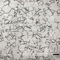
When ASTM standard E 2 was published in 1917, ASTM Committee E-4 on Metallography’s first standard, it described the planimetric method for measuring grain size based upon publications by Zay Jeffries, a founding member of E-4.

Jeffries was a graduate student under the famous Harvard professor, Albert Sauveur. Sauveur published a paper in 1894 where he defined grain structures in terms of the number of grains per square mm at 1X. But, he did not develop details on his method. This method is more tedious to use than the Heyn intercept method because a count of the grains must be made by physically marking the grains as they are counted, when done manually. Experiments were conducted to determine the influence of the number of grains counted per grid application using the Jeffries planimetric procedure of ASTM E 112 with a single test circle of varying size. Results show that this is a viable test method and produced good data down to relatively low count numbers per grid application. Bias was not observed at low counts, only data scatter.

Measurement of Grain Size in Twinned FCC Alloys

September 24, 2012 by George Vander Voort

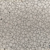
Measurement of Grain Size in Twinned FCC Alloys

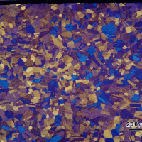
Grain size is probably the most frequent microstructural measurement due to its influence on properties and behavior/service performance. Grain size can be determined by several methods. Chart comparison ratings are probably the most often performed, as this method is fast and simple. But its accuracy is at best ± 1 G value.

An ASTM E-4 interlaboratory round robin test using Plate I of ASTM E 112 showed that chart ratings were biased with the rating being ½ to 1 G value coarser than the actual measured grain size. Similar studies have not been conducted with Plates II or III. Actual measurements of grain size are done by either the planimetric or the intercept methods, as defined in E 112. These are unbiased methods, as long as the grain boundaries were properly delineated by the etchant. Experience has shown that measuring the grain size of BCC metals is much easier than measuring the grain size of FCC metals and alloys that contain annealing twins. ASTM E 112 has two comparison charts for such metals; Plate II for specimens that exhibit a so-called “flat” etch appearance and Plate III for those that exhibit a grain contrast etchant response. Plate III was developed using copper specimens and the images are at 75X, while the other E 112 charts are at 100X. To further confuse the issue, Plate III expresses grain size in terms of d, the average grain diameter, calculated by taking the square root of the average grain area (which is the reciprocal of the number of grains per mm2), rather than as an ASTM grain size number, G.

Measurement of Grain Shape Uniformity

September 15, 2012 by George Vander Voort

Measurement of Grain Shape Uniformity

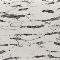
Cold working is well known to change the properties of metals and alloys. Deformation increases the strength of metals but usually reduces it toughness and leads to anisotropy of properties, that is, directionality. Hot working also produces similar affects, the microstructural results after hot work with low finishing temperatures may appear to be the same as from cold working.

Hot rolling of shapes, plate or bar, for example, elongates the nonmetallic inclusions in the deformation direction, which will reduce the isotropy of mechanical properties. Hot working can also lead to segregation being elongated parallel to the deformation direction, which also reduces isotropy. Reducing the finishing temperature, that is, the temperature of the steel at the last deformation pass, will promote “banding” – parallel alignment of the constituents into layers, such as alternate bands of ferrite and pearlite. This also promotes anisotropy of mechanical properties, chiefly toughness and ductility. Strength is not usually affected to a significant degree by banding, compared to toughness and ductility.

Metallographic Procedures for Precious Metals

July 23, 2012 by George Vander Voort

Metallographic Procedures for Precious Metals

Relatively few metallographers work with precious metals, other than those used in electronic devices.  Precious metals are very soft and ductile, deform and smear easily, and are quite challenging to prepare. Pure gold is very soft and the most malleable metal known. Alloys, which are more commonly encountered, are harder and somewhat easier to prepare.

Gold is difficult to etch. Silver is very soft and ductile and prone to surface damage from deformation. Embedding of abrasives is a common problem with both gold and silver and their alloys. Iridium is much harder and more easily prepared. Osmium is rarely encountered in its pure form; even its alloys are infrequent subjects for metallographers. Damaged surface layers are easily produced and grinding and polishing rates are low. It is quite difficult to prepare. Palladium is malleable and not as difficult to prepare as most of the precious metals. Platinum is soft and malleable. Its alloys are more commonly encountered. Abrasive embedment is a problem with Pt and its alloys. Rhodium is a hard metal and is relatively easy to prepare. Rh is sensitive to surface damage in sectioning and grinding. Ruthenium is a hard, brittle metal that is not too difficult to prepare.

The Value of Color Metallographic Techniques in the Study of Welds

June 21, 2012 by George Vander Voort

The Value of Color Metallographic Techniques in the Study of Welds

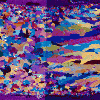
Welding is a very important joining process and has been used extensively for at least the past 75 years. There is a need to control processes, such as welding, to insure a high quality end result. Over the years there have been many spectacular failures of welded structures, starting with Liberty ship and T-2 tanker failures during WWII, that emphasize this need. Many procedures involving non-destructive and destructive tests are used to study weldments.

Metallographic examination can be performed in-situ by grinding an area on the surface of the weld, its heat affected zones and adjacent base metal (the metal being joined that was unaffected by the temperature of the welding process). This is a reasonably non-destructive evaluation. Destructive examination, where a specimen is removed from either the welded assembly or test coupons, is quite commonly performed. Test coupons are often used to qualify the welder and ensure that the techniques and materials chosen will produce a weld with acceptable soundness and mechanical properties. Post mortems of failed weldments are also examined metallographically using sections removed from the welded assembly, generally after non-destructive examination is completed.

Bias in Grain Size Chart Ratings

May 14, 2012 by George Vander Voort

Bias in Grain Size Chart Ratings

When I worked for Carpenter Technology Corporation in their research center, we encountered several cases where chart ratings of specimens by their production lab yielded grain size ratings between 4 and 5 for a number of specimens on an order (these orders required tests on 20 specimens from different bars). When we re-tested them in the R&D center, we got similar chart ratings. But, when we actually measured the grain size, all ratings were between 5 and 6 on the ASTM E 112 scale. As the criterion for pass/fail was a grain size of 5 or finer (higher), this bias was important. Consequently, at a subsequent ASTM E-4 committee meeting, I conducted a “round robin” test. 

Metallography and Microstructure of Aluminum and Alloys

April 14, 2012 by George Vander Voort

Metallography and Microstructure of Aluminum and Alloys

Compared to many other metals and alloys and many other materials, such as carbides, ceramics and sintered carbides, aluminum and its alloys are low in strength and hardness. Aluminum is a soft, silvery metal with a face-centered cubic crystal structure, a hallmark of ductile metals. Its softness makes it somewhat difficult to prepare but the alloy is not sensitive to problems that plague preparation of magnesium and titanium, that is, a sensitivity to mechanical deformation that generates mechanical twins or Neumann bands. Aluminum, like chromium, niobium and titanium, is very corrosion resistant and a thin, transparent oxide film will form on a freshly polished surface. This film is responsible for its good corrosion resistance, but also makes etching difficult. Aluminum alloys contain a rather high content of intermetallic precipitates that contribute little to improving the alloys and may be detrimental. Contemporary four or five step preparation procedures are given for preparing aluminum and its alloys. Results are also shown for revealing grain size with Weck’s reagent, a useful alternative to anodizing. 

  • « Previous Page
  • 1
  • …
  • 4
  • 5
  • 6
  • 7
  • 8
  • Next Page »
  • Vacuum Heat Treating: Education & Training
    • News & Announcements
  • Vacuum Technology with The Heat Treat Doctor
  • Vacuum Pump Technology: Education & Training
  • Metallography with George Vander Voort
  • Q’s and A’s
  • “What’s Hot!” Newsletter
  • Glossary Metallurgical Terms
voort
Vertical vacuum furnace specifications
horizontal vacuum furnace specifications
Vacuum Furnaces
Vacuum Furnace Zone Rebuilds
Technical Articles and Resources

Specialists in Vacuum Furnace Technology - High Quality Vacuum Furnace Manufacturer

COMPANY

  • VAC AERO Products & Services
  • Company History
  • Certificates & Approvals
  • Employment Opportunities
  • Values & Commitment
  • Corporate Sponsorship
  • Corporate Brochure
  • Terms & Conditions of Use
  • Privacy Policy

FURNACE MANUFACTURING

  • Horizontal Furnace Specs
  • Vertical Furnace Specs
  • Hot Zones
  • Control Systems
  • Custom Vacuum Furnaces
  • Quality Control
  • Service & Support
  • Furnace Request For Quote (RFQ) Form

THERMAL PROCESSING

  • Ontario – Plant 1
  • Ontario – Plant 2
  • Quebec – Thermal Processing Division
  • Specific Heat Treating & Brazing Approvals
  • Metallurgical Services Matrix

COATINGS

  • Quebec Coatings Division
  • HVOF Spray System
  • Specific Coating Approvals
  • Metallurgical Services Matrix

SERVICES & SUPPORT

  • Furnace Rebuilds & Upgrades
  • Hot Zone Rebuilds
  • Process Controls Upgrades
  • Ordering Parts
  • Field Service
  • Training Seminars

© Copyright 2016 VAC AERO - All rights reserved. Site Map Contact Terms and Conditions Privacy